
An acoustic camera produces an image where the intensity of each pixel represents the amplitude of acoustic waves coming from the corresponding direction. This is akin to an optical camera producing an image where each pixel represents the intensity of light coming from the corresponding direction.
For an optical camera, the lens focuses light coming from a certain direction to the corresponding pixel on the sensor or film. Each pixel in the image represents the intensity of light coming from a specific azimuth (angle in the horizontal plane) and elevation (angle in the vertical plane). The lens does this by slowing and delaying the electromagnetic (light) waves hitting the lens, by precisely the right amount, so that all waves coming from a certain direction arrive in phase in the focal plane, at the position of the corresponding pixel.
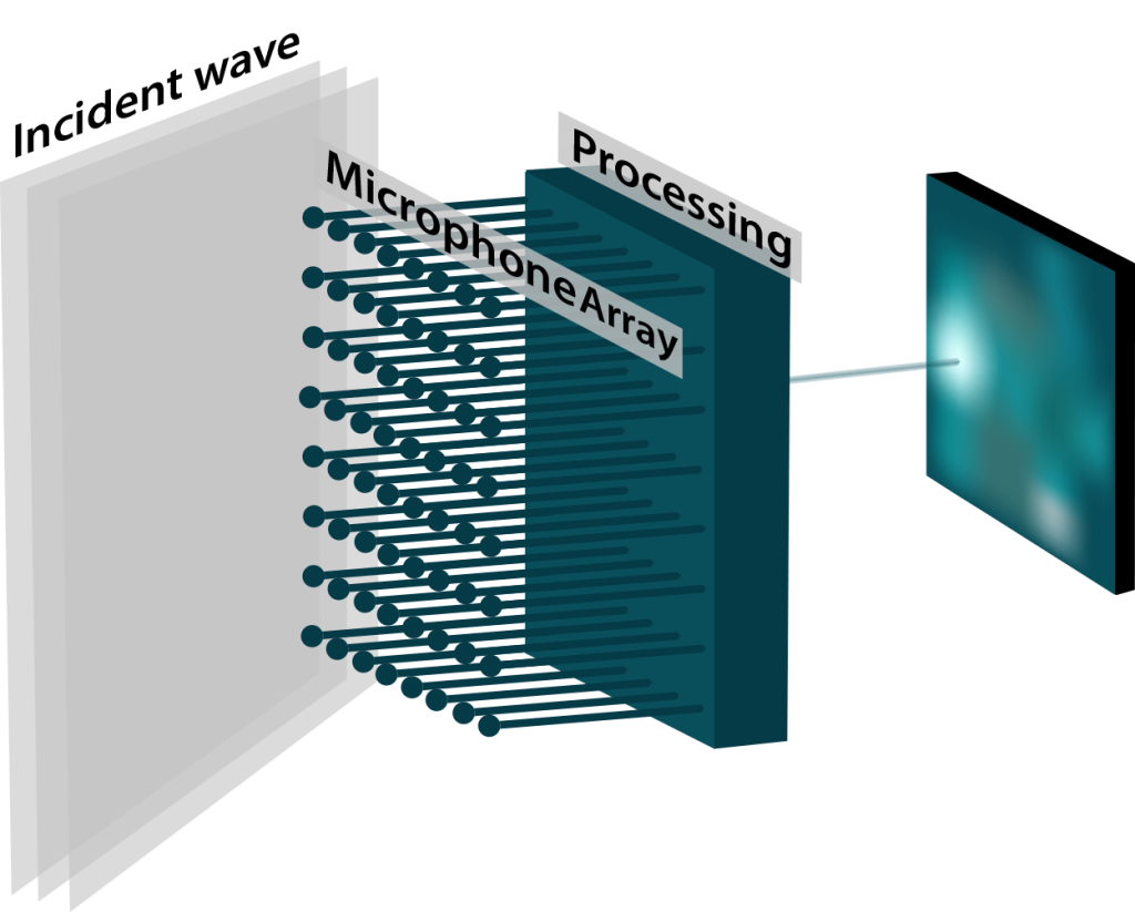
An acoustic camera does much the same thing, except that the work of the lens is replaced by a digital computational engine that processes signals captured by an array of microphones (see Figure 1).
Frequency, Aperture Size, and Image Resolution
For an optical camera, as well as for an acoustic camera, the image resolution is a proportional to the ratio of aperture size to wavelength.
For an optical camera the aperture size of the camera (the size of the lens or more generally the light collector) is always very large relative to the wavelengths of interest. This is true even for very small lenses, such as those found in camera phones, where the size of the lens is a few mm, while the wavelengths of interest are in the hundreds of nm (more than 10000 times smaller). For an optical camera, resolution is rarely limited by the size of the aperture.
For an acoustic camera on the other hand, the frequencies of interest often extend to quite low frequencies (long wavelengths). For instance, the wavelength at 100 Hz is 3.4 m. To have a reasonable resolution at such low frequency would require an array of at least 8 to 10 times as large (25 to 30 m wide). This is usually not practical. Therefore, for acoustic cameras the resolution is typically poor at lower frequencies and improves only as the frequency of interest increases.
Spatial Sampling and Upper Frequency Limit
For an acoustic camera, the maximum frequency is limited by the spatial separation between two adjacent microphones. The half wavelength of the maximum frequency sampled by the microphones must be wider than the distance between two microphones. Otherwise, the array is not able to distinguish between sources that are within the field of view, and sources that are outside, leading to artifacts such as phantom images.
For ACAM_64, the distance between microphones is 23 mm, so that frequencies up to 7.5 kHz can be imaged properly. In practice the array is sampled at 16 kHz, with a Nyquist frequency of 8 kHz. The anti-aliasing filters in the camera ensure that the signal energy is low above 7.5 kHz.
Field of View (FOV)
The field of view of a camera represents the number of degrees that the camera can see (that are represented in the image) in the horizontal plane (azimuth) and vertical plane (elevation).
For ACAM_64, the field of view is the same in azimuth and elevation (the image is square). There are two possible settings:
- 90 degrees (-45 degrees to +45 degrees from left to right and from bottom to top)
- 60 degrees (-30 degrees to +30 degrees from left to right and from bottom to top)
Audio Beamformer
The acoustic “sum” signal corresponding to any pixel position is available and can be streamed out of the processing engine, to be listened to. This process is called “beamforming”. The microphone array can be digitally steered to the angle of incidence corresponding to any pixel in the field of view and focus on that source. In addition, since the image shows the azimuth and elevation of the loudest source in the field of view of the camera, the beamformer can be made to follow that “hot-spot” as it moves across the field of view.